
What Affects Real-World RF Performance
What affects real world RF performance?
RF is sometimes seen as a kind of "Black Magic", where things behave in some mysterious unfathomable way. In other cases, it is treated like just an add-on to standard digital electronics with little special attention needed. The truth is, RF follows predictable rules, but it is a fundamentally analogue world, and subject to a number of subtle effects and behaviours.
When designing an RF product, one of the first numbers you will look at is the output power of the radio – the strength of the signal sent out. Taken together with receive sensitivity – the level of signal the radio needs to receive to be able to interpret the data being sent – a simple calculation can give you a range over which your radio can send and receive data. (I am assuming for simplicity we are discussing two identical radio transceivers). There are many online calculators that can do this for you e.g. RF To Distance Calculator
However this is only a theoretical number and not particularly useful for practical purposes. What we will look at here is what factors affect the real world performance of radios, and what you might be able to do to mitigate them.
Firstly, there is the antenna. A radio chip only presents a signal at an output pin. The antenna (and any intermediate cabling/connections) is what transforms this electrical signal into radio waves. If we assume we don’t necessarily know where the transmitter and receiver will be positioned in relation to one another, then the ideal antenna is one that transmits uniformly in all directions, and is unobstructed through 360o of solid angle. Whilst something close to this might be achievable in some specific scenarios, for most applications, real world constraints mean the antenna will have some directions with a much weaker signal than others. Radio signals are also polarized, and the relative polarization of radio signals may be variable, which will also reduce effective range.
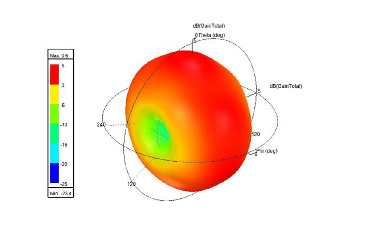
Radiation Pattern of PCB antenna. Power is reduced in PCB plane.
Application Electronics
In the ideal case, the antenna would be placed separate from any electronics or casing, connected via a (lossless of course!) cable. This isn’t practical in most cases, and frequently, what is desired is that the antenna is integrated onto the application PCB – typically either a chip or trace antenna. In such a case the placement of the antenna on the PCB and the layout of other components can impact the performance.
A good design would typically have a “keep out zone” around the antenna, where no other components would be placed, and also a good length of “ground plane” – a length of the PCB connected to ground with few blockages on its path. This length should be at least ¼ wavelength. This acts to stabilize the radio signal. Recommended Keep Out zones for Insight SIP modules are in the product data sheet - e.g. isp_ble_DS1507.pdf section 4.3. An Application Note on the effect of different ground planes is available here
Large items such as a battery could be problematic if placed too close to the antenna, and so this is a further point to consider.
Of course, these ideal parameters may not be achievable, particularly if size is a application constraint (for instance in a wearable or portable device).
Casing and Surroundings
If we have an optimally designed PCB given the constraints, the next issue is the casing of the application and the environment in which it sits. There are several factors to consider, but to put it in simple terms, any metal (or conductive materials) in the vicinity of the application PCB is going to be bad news. That’s not to say any nearby metal with totally ruin performance, just that it will have a negative impact.
Also, the human body can have a significant effect on RF performance, which is relevant for any wearable device. The level of the effect is dependent on the RF frequency in use, but for popular technologies such as Bluetooth and Wi-Fi using 2.4 – 5 GHz, the absorption is significant.
Beyond the immediate vicinity of the application device, the larger environment will also affect transmission. Walls, people, or other obstructions will impact performance. Even walls not in the direct “line of sight” path between a transmitter and receiver can produce reflected signals which can impact radio performance. An outdoor application will have fewer issues, by contrast.
What can Insight SIP do to assist?
Our integrated modules take care of the antenna part of the problem, and our multi-decade experience of miniature antenna design mean we can provide products that optimize performance and space.
We are happy to review customer’s PCB layouts to identify any possible issues before embarking on production, to avoid wasted design cycles
We can review product mechanical designs, and advise on placement of our modules, and arrangements of the customer PCBs. We can produce estimates of the probably degree of performance degradation in many scenarios where non-ideal conditions are inevitable.
If there are performance results that are not easily explained, we can engage in detailed simulations to understand what the issues are.
Conclusions
Ideal performance is rarely achieved in real life. Following good design practice can optimize results. However, real world constraints and product marketing considerations have to also be accounted for.
Most applications don’t need perfect performance, the real question is whether the performance is good enough to meet the requirements. Real world testing in realistic scenarios is ultimately required to validate that an application can work effectively.